More Woodturning Magazine
https://www.morewoodturningmagazine.com
This Article was printed exclusively for More Woodturning Magazine subscriber:
Kurt Hertzog at: kurt@kurthertzog.com
Articles
October 2019
 Click ad to visit our sponsor
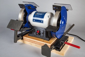
Every woodturner needs a sharpening system. Without one, every tool turns into a scraper. Incapable of making a clean cut, the clearance angle is continually increased until the tool makes dust. Sharpening is such a key skill that needs to be learned as part of a new turner introduction to woodturning. I dare say that the skill levels attained by any turner will certainly be negatively impacted by their poor sharpening skills.
When I started turning many years ago, I had no existing grinder for a sharpening system so I had the opportunity to start at ground zero. Having grown up with and having many years of involvement with machinists and their tool rooms, I naturally wanted to buy the “best” grinder I could. I bought a Baldor 7” grinder. Buying it new in spring 2001, I had the luxury of buying a high or low speed. I bought the low speed having been told that low speed was the way to go. At the time it made sense. Low speed would let the newcomer have more forgiveness for errors and poor sharpening technique. Also, it was supposed to create less heat. More on these myths later. Why a 7” grinder? I really wanted an 8” because I liked that gentler hollow grind much more than the 6” radius. Because I’m cursed with back problems, an 8” was far too heavy since my sharpening system needed to be mobile. The 7” grinder was the choice since it had a more acceptable radius than the 6” and it was more luggable that an 8” ever could be. The Baldor grinder I have is a ½ hp, 7” made with the traditional cast iron frame and housings. Not only is it built like a tank but it is designed and executed with perfection. Cast iron tool rests that position on rails for repeat positioning are just one example of the grinder's well planned features. Painted with the trademark Baldor grayish blue, the grinder alone tips the scales at just over 71 pounds without the base and attachments. My Baldor grinder has served admirably and it works as well as it did almost 20 years ago. That said, my back hasn’t and I’m forced to create a new sharpening system that is much lighter and has the same attributes.
|
|
|
|
|
|
|


Designing a Sharpening System – The Grinder
As you plan your sharpening system, you need to consider a few things that have a big impact on choices. First and foremost, is it a stationary system? If it will sit in your workshop and rarely if ever get moved, you won’t be concerned about the weight and also will have some luxuries on size of the overall system. A movable system, whether from one location to another in the shop or building, or in the car to distant locations for use, needs to be light enough to manage and small enough to be packed. With that decided, you need to consider what diameter wheels you wish for your grinder. The common 6", 7", or 8” grinders are widely available with 7” being a bit of an odd ball. Among the commercial users, it is fine but for the weekend warriors, a 6" or 8” and their respective wheels are more widely available in the retail market. You can pick which ever suits you based on your experience, the pricing of the various sizes, or simply what you have been using to date. If your tools have been ground at the workshop where you learn or at the club having been ground on an 8” wheel, why change? If it was a 6” and you’re happy with it, again why change? Once you’ve decided on a size grinder, the next decision is price. You can buy 6” grinders in the import tool stores on sale for $39. Should you? I don’t recommend it but it’s your choice. My 7-inch Baldor grinder cost me $280 discounted in 2001 and it currently sells at the same place for $670. When and if I ever sell my grinder, I can certainly expect my original investment back and probably a nice profit based on the continued expected lifetime. The next owner should get another 20 years of service or more. My grinder wasn’t an investment in the stock market but at least after 18 years of use, getting my money back and then some isn’t bad. For my new sharpening system, I chose a Rikon 1/2 HP, 8” grinder available from Woodcraft for a little over $100 on sale. That selection gets me to 8” and is very light in comparison to the Baldor. The manual says it tips in at 35 pounds. Is it Baldor quality or performance? Certainly not, but I don’t think you can expect that at the Rikon price point. Besides, at least I’ll be able to carry this up the stairs to the car when needed. I didn’t go to a more expensive grinder because I don’t know of anything between the quality bargain brands and the tool room grade grinders at a reasonable weight. My selection of the Rikon was based on cost, size, weight, and quality. The cost is very reasonable since I plan on making two or three systems. I will have one at each turning area in my two workshops. I’ll also have a traveling system that is easily loaded in the trunk without disrupting the turning stations or their operation. The other reason for selecting the Rikon is their tool rests. The Rikons that I bought have been redesigned and are dramatically improved. Gone are the flimsy bent steel rests fastened to the wheel safety guards with sheet metal screws. They have implemented functional rests that are adjustable and high enough quality to be built upon. In my opinion, they are far too small and the adjustment locks are not suitable but I can modify both of those to be to my liking. More on those features later. The grinders are well made for their relatively low price. They spin up to speed a bit slowly but once at speed, they run very true. They’ll serve well in my system with a few modifications.
|
|
|
|
|
|
|


Designing a Sharpening System – the Grinding Jigs
When you learn to sharpen, you will probably take advantage of grinding jigs. That helps with repeatability. Once you’ve mastered sharpening, most do a combination of freehand and using jigs. The jigs play a part in sharpening those special grind tools or just being an on-going aid to sharpening. Regardless of how you use grinding jigs, I think it should be a part of any sharpening system. There are many to choose from. Some handy folks make their own. Other rely on the systems available from the retailers. I’ve used virtually everyone that is made and all of them work fine. Some operate differently than others but they all get to the same end--a tool held accurately to sharpen the tool in a controlled and repeatable manner. For my system, I selected the Wolverine system by Oneway. I’ve got it on my current Baldor setup and am used to it. Over the years, I’ve accumulated all of the accessories for it. I like the way it works so it is the other key component in my new sharpening system.

Photo 9: I have used the Oneway Wolverine system for nearly 20 years and have been satisfied. You can pick your own favorite aftermarket sharpening jig provider.
Designing a Sharpening System – the base
If you are creating a fixed location sharpening system, you can simply mount your grinding jig bases and the grinder directly to the bench. It will be stable and stay aligned as you mount it. My recommendation is to always build a movable system. If you build your sharpening system on a baseplate of sorts, you can move it should you wish. If you never need to move it, screw the baseplate to the bench or just use a couple of clamps. For the cost of a baseplate, you have plenty of flexibility in location and the option to make it a traveling system if needed. Since my systems are planned to be mobile, I need to design the baseplate with a couple of considerations. First, it needs to be large enough and thick enough to properly mount and fasten the grinder and the grinding jigs hardware. Rather than leave the rubber feet on my grinder, I plan to remove them per the Oneway Wolverine instructions and bolt the grinder directly to the baseplate without them. They are installed on the grinder to keep it from walking around on the bench if it isn’t rigidly fastened. Not really the situation in my case. The Wolverine hardware calls out the mounting locations with respect to the grinder wheel locations. Following their instructions and trying to minimize the size of the baseplate for transportability, my initial planned baseplate dimensions were 8” x 20” x 1”. Long enough for the grinder and grinding jig mountings, deep enough for mounting and handling, and thick enough to mount things properly. There is also sufficient room to clamp the base to another bench: a good feature when traveling and using the sharpening system on the road. A couple of quick clamps do the job nicely. I will use wood screws from the top to mount the Wolverine hardware and carriage bolts from the bottom to mount the grinder. The carriage bolt heads will be recessed into a countersink to make the bottom flat and scratch free hence the 1” thickness. You can make your design as large as your needs dictate. My suggestion is to err on the larger than needed size. Should you find that the width or length needs to be trimmed for some reason after you’ve completed mounting everything, it is easily done. It is far more difficult to stretch the wood base sizes afterwards. You are welcome to use whatever suits you for a base if you are using one. Rather than cut my base materials out of sheet goods, I opted to purchase it at Home Depot. I bought a 3-foot length of stair tread. Thick enough, long enough to cut my desired lengths, and more than wide enough. Again, easily cut to my sizes on the band saw or table saw in your shop or with a hand saw if needed. In order to minimize cuts to fit an arbitrary set of dimensions, I opted to simply cut the stair tread in half yielding two base plates of 18 x 11 ½ x 1 inches. This sizing is certainly capable of filling my mounting needs.
|
|
|
|
|
|
|


Sharpening system - wheel selection
Normally, I’d wait until the system was done to make any changes to the grinding wheels on the grinder. Since this system will have the alignment on the baseplate located based on the edge of the grinding wheels, I’ll take care of this first. You may have the luxury of waiting or--even better--using the wheels that were provided on your grinder. My Rikon grinders were delivered with the usual wheel selection and setup. They have a 60 grit and 120 grit wheel installed. In the traditional tool room mentality, this is a typical setup. The coarse wheel is for grinding where much stock will be removed. The coarse grit rapidly removes the stock generating less heat that a finer grit wheel would. The finer wheel is for light, more precise grinding. The 60 grit will work well for grinding tool bits and other general shop needs. My choice is to get rid of both wheels and install two new wheels of the same grit. In my sharpening system, I dedicate one side of the grinder to my cutting tools and the other side is for my scraping tools. As such, the rests are set appropriately, locked in place, and never adjusted. I can then walk to the grinder and sharpen nearly all of my tools free hand quickly and efficiently. When I need to sharpen tools requiring a special jig or a different angle, I have the Wolverine system available to precisely hold those tools. In the sharpening system under construction, I chose to use CBN wheels. I purchased mine from Woodturners Wonders but there are many sources for CBN wheels. Feel free to pick your own source of CBN or AlO2 wheels. The wheels on my grinders are removed and will be sold to anyone needing them. They are brand new and of reasonable quality so they’ll be a good buy for someone in the club. My selection of grits for the grinders is a bit odd and needs some explaining. On my original Baldor sharpening system, I installed two identical 60 grit wheels, each side being set as noted--left side for sharpening cutters and right side for sharpening scrapers. The choice of 60 grit sometimes brings questions. Why so coarse? Why not a fine wheel to get that very smooth, keen sharpened edge? The 60 grit does shaping and sharpening well enough for my needs. The second grinder will receive 350 grit CBN wheels.
|
|
|
|
|
|
|
|
|
|
|


Photo 20: While you may get away with finger-tightening the nut, I like to put a wrench to it just to snug it up. I hold the wheel by hand only and give the nut a quick snugging.
Sharpening system - Layout
If your needs require you to mount things offset, go ahead. If you have no special needs for that, make everything symmetrical. With my base being 18 inches, I’ll have my grinder straddle the 9-inch line through the base plate. Its location front to back is determined by the grinding jig instructions. The front edge of the grinding jig hardware is to be located at the front edge of the baseplate (or bench if hard mounted) with the edge of the wheel diameter at that location. You can do some fancy measuring and planning if you wish. I simply marked the bolt location lines on each side of the 9-inch line and slid the grinder forward using a square to indicate when the wheels were at the front edge. Obviously that wheel location will move rearward over time if your wheels get smaller. AlO2 wheels will reduce diameter over the years but it won’t be enough to impact anything. I’m replacing my OEM wheels with CBN wheels so there never will be any reduction in wheel diameter. If your grinding jig mounting instructions differ, use those as indicated to layout and mount your grinder and jig bases. My layout needed to comprehend the outer wheel position with respect to the jigs and the edge of the baseplate. Follow your manufacturer's specific instructions.
|
|
|
|
|
|
|


Shimming up the grinder
The Oneway Wolverine instructions recommend that the centerline of the grinding wheel be approximately 6 ½” above the baseplate where their grinding bases are attached. With the feet removed from my grinder, I was 1 ½ inches short of that height. Some scrap plywood glued together to make up my 1 ½ inch spacer platform worked nicely to achieve their recommended dimension. Your grinder and grinding jig manufacturer's instructions may vary but the concept is the same. They want to have a fixed geometry for their product to work in so it performs as designed. Will things work at a different positioning of the grinder to the jigs? Sure, but why not try to be in their window of operation if possible?
|
|
|
|
|
|
|


Miscellaneous Assembly
Whenever is convenient, you can assemble the miscellaneous items. They are key and do need to be done but it is not important to the project when you fit them in. Obviously the tool rests are important. As designed and delivered, they have serviceability but that can be improved later on with some modifications. Assemble them as indicated in the Rikon instructions. My longer-term plan is to add additional metal to the tool rest platform to increase the size and add a bit of mass. I also intend to remove the thumbwheel nut and replace it with a nut requiring a wrench. That will let me adjust the rests as desired and lock them into place. Still changeable with a wrench, but not for the casual passersby. Also, assemble and install the spark guards and safety shields.
|
|
|


Photo 31: Assemble and attach the eye safety and spark shields. They are easily attached and are adjustable as needed. Do not rely on these alone! Always wear your PPE when grinding.
Fabrication of baseplate
Depending on your experience and shop facilities, your baseplate fabrication may be a breeze or a bit of a challenge. Because I chose a stair tread as raw material, I only need to make a single cut to make two bases. I’ll make my cut on my chop saw but you can easily make your baseplate with a table saw, band saw, or hand saw if needed. The same with the drillings. I’ll use my drill press but there is no reason why you can’t make all of the necessary drillings and counter sinks with a pistol drill. I’ll cut my bases to size and layout my hole locations. The baseplate is cut to your plan dimensions from whatever stock you’ve selected. In my case, I cut the stair tread to 18 inches overall. Because the stair tread was purchased already having the bull nose front edge, rather than cutting it off I worked it into the design. Everything is symmetrical above the 9-inch line across the base plate. The Rikon grinder instructions show the mounting holes to be 6 5/16” apart and 7/16” in diameter. If your manufacturer doesn’t provide the hole location dimensions, they can be easily measured. Once the grinder has been properly located and the holes marked, position and mark the grinding jig hardware per the manufacturer's instructions. In my systems, I marked my center axis at 9 inches, laid out the grinder mounting holes center lines to have the grinder straddle that line, and then brought the grinder wheels to the edge of my mounting base. To find the correct position, I installed the wheels I intended to use. They were CBN wheels. They were installed per the manufacturer's instructions and using their spacing hardware. While the side shields aren’t really needed on CBN wheels as they are with AlO2 wheels, there is no reason not to reinstall them. For how often I might ever need access to change wheels, I am certainly willing to remove the side shields. To locate the grinder properly, I used a square at the edge of the baseplate and slid the grinder up until the grinding wheel was touching the square. Use whatever you have as a square to perform this. It doesn’t even need to be a shop square. You can use a cereal box for your edge detection if needed. Once the grinder is properly located on the mounting lines and positioned front to back, the mounting holes are marked. The grinding jig hardware is positioned with the diamond located at the centerline of each of the grinding wheels. This really can be eyeballed but feel free to lay it all out per the dimensions if you wish. I eyeballed the location, but did ensure that the jig was properly square with the baseplate. Those mounting locations were marked. The Wolverine bases have an eccentric cam arrangement that locks the arms into position where desired. The eccentric cams are activated by levers that swing out to lock things in place. Because the base allows these cams and arms to be repositioned if desired, think about how you want the swings to operate. You can move the mechanisms after mounting, but life is far easier if you do it now. The base plate is ready for drilling the pilot holes for the wood screws and the through holes for the grinder mounting bolts. An unnecessary but nice optional touch is a clamp or two to clip the commonly-used grinding jig pieces to the base. Very handy when traveling to keep things from being forgotten, lost, or clunking around. Another feature to consider is a way to store the cord when traveling or perhaps just excess cord when in the shop. I located a couple of holes in a clear space towards the back edge of the baseplate. These holes will be for the mounting screws to come through the bottom and hold a couple of yet-turned knobs. These will be sized and shaped so I can wind the cord around them keeping it neat when moving the sharpening system.
|
|
|


Drilling the holes
I’m going to use one of my drill presses to drill the holes in my baseplate. If you don’t own a drill press, you can easily accomplish this with a pistol drill. I like to have all of my hardware in hand before I drill any holes. This way, I can drill the proper sized hole for each of the fastener types. I find this far easier than putting holes in place and then going to the store to get the necessary hardware to fit the holes. We aren’t making rocket parts but good practices don’t hurt. I always put a center punch to all of the locations where I intend to drill. You don’t need to, but with a center location marked, your drill will position accurately. Not needed here, but a center location helps keep smaller diameter drills from wandering when you start the drilling. You can center mark your hole locations with a punch and hammer, a spring-loaded center punch, a hand awl, or even a nail and hammer. The holes can be drilled in any sequence you wish. Since my mounting screws for the Oneway hardware are wood screws, I’ll only be putting a pilot hole in place. That drill will be a good one to put pilot holes in all of the other locations for the larger drillings. Once the pilot holes are in place, you can drill the larger holes with the desired sizes whether a clearance hole for the bolts or part of the screws or a tight-fit pilot for the screw threads. One thing I do before drilling the grinder mounting holes is counter sink for the bolt heads on the bottom using a Forstner bit. It is sized for the flat washer used with the bolt and deep enough for the bolt head not to protrude beyond flush with the bottom. Once this has been done, the bolt hole drilling can easily be done and properly centered using the Forstner guide point depression.
Assembly
With the grinders completed having the wheels changed (if you wish), the hardware all purchased and ready, spacing blocks made, and the aftermarket grinding fixtures ready, it is simply a matter of assembling everything with the proper fasteners. I use a drill with the driver inserted and the clutch set appropriately to drive all of the screws. The bolts for the grinder are pushed through from the bottom and the grinder set in place on those bolts. Even though I use a flat washer and lock washer under the nut on the top of the grinder base, I still put a dab of blue Loctite on the threads. It is at hand and won’t hurt anything. The lock washers should keep the nuts from loosening but with the Loctite, all is vibration-protected in spades. Always use the blue Loctite for things you may want to disassemble later on. The red Loctite works equally well if you never expect to take things apart. You can break it free but it takes a torch, so stick with the blue.

Photo 34: With the holes drilled in position and to size, everything drops into place. Final assembly is 5 minutes maximum with your power driver and socket wrench.
Completed Project
I built two grinding stations that are identical except for the wheel grits. One had 60 grit and the other has 360 grit. The coarse grit is the same as I use on my current AlO2 7-inch Baldor set up--coarse enough for shaping and still fine enough for sharpening. The 360 grit sharpening station will be used for sharpening only and will provide the finer ground pattern on my tool edges. Two items left undone but will be tackled shortly. Some turned pegs to mount behind the grinder to wind the power cord around will make for a neater traveling package. These can also be used to take up power cord slack that is unneeded to reach the power outlet. More important to me is the grinder platforms. As provided, they are workable but not ideal in my opinion. I intend to adapt those platforms by gluing larger metal plates to the existing platforms. I’d like something a bit larger to work on and something with a bit more mass than the casting provided. I’ll sketch out the shape and size I want and fabricate them in steel. Once completed, those plates will be fastened to the existing platforms with epoxy.

Photo 35: My end point with two portable sharpening systems completed. One with 60 grit CBN and other with 350 grit CBN. Rather than 80 pounds, each weigh under 40 pounds.
Conclusions
This was an easy project to do with minimal tools and a straight forward process. Creating your own sharpening station can use the grinder you already own or you can decide to purchase one. It can be high or low speed since both work nicely to accomplish the end goal. You certainly can create your system without any additional grinding jigs but I think you’ll find the Wolverine or other choices available will add plenty of value and flexibility. While my systems aren’t totally complete as of this article, I’ll get my grinding platform modifications underway to increase their size and mass. The power cord wind-up knobs will take a few minutes at the lathe and will be mounted shortly. How much do you want to spend? Your choice. New or used components? Again, your choice. AlO2 or CBN wheels? You choose. Regardless of the path you select, I can assure you that a sharpening system that you know how to use can only improve your turning results. The number of turners that plateau far too low on the skill scale can almost always be attributed to poor fundamentals and/or poor sharpening skills. Give making your own vision of a sharpening system a try.
Click here to read about the author, Kurt Hertzog.
Submit Questions / Feedback on this Article
